
Mastering DIY digital fabrication means learning to bridge the gap between a 3D model and the actual G-code for your CNC. One of the most common hurdles for beginners in Open Source Fabrication is the “disappearing tool path” when creating pockets in FreeCAD’s Path Workbench.
In this tutorial, we’ll explore how to solve common pocketing issues, ensuring your Maker Education journey stays on track.
1. The Setup: Creating your Geometry
Before we jump into CAM (Computer-Aided Manufacturing), we need a solid foundation.
- Design in Part Design: Start by creating a simple body and a sketch. For this exercise, a rectangular block with internal slots is perfect.
- The Through-Slot: Create a rectangular profile and use the Pocket tool to cut through the entire material.
- The Blind Pocket: Select a top face, create a new sketch, and pocket it to half the material depth (e.g., 5mm).
2. Moving to the Path Workbench
Once your model is ready, switch to the Path Workbench to generate the CNC instructions.
- Create a Job: Click the “Create Job” icon. This wraps your model in a “Job” container that holds your tools and operations.
- The Selection Challenge: For a through-hole, you must select all vertical internal faces. Use the Alt + Mouse to rotate and Ctrl + Click to select multiple faces.
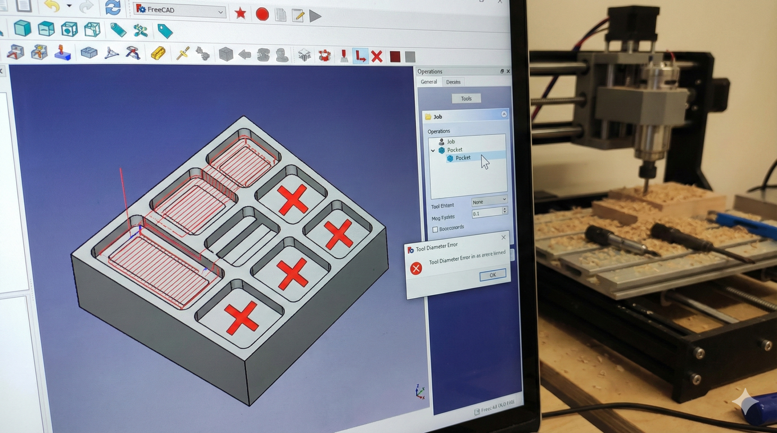
3. Problem Solving: Why is my Tool Path missing?
You’ve selected the faces, clicked “Pocket,” but nothing appears? This is the most common “bug” that is actually a configuration mismatch.
- The Tool Diameter Rule: If your CNC bit (Tool) is wider than the pocket you designed, FreeCAD simply won’t generate a path.
- The Fix: Double-click your Default Tool in the Job tree. Reduce the diameter (e.g., to 1mm or 2mm) to fit inside your geometry.
- Consultant Tip: In Prototipagem (Prototyping), always match your digital tool to the physical bit you have on your workbench!
4. Refining the Finish: ZigZag vs. Spiral
FreeCAD defaults to a ZigZag pattern, which can leave “jagged” edges on your final piece.
- Spiral for Quality: For a cleaner finish on your DIY projects, change the pattern to Spiral.
- How to change it: Go to the “Operation” tab of your Pocket object, find “Pattern,” and switch from ZigZag to Spiral. Apply, and you’ll see a much smoother tool path.
5. Simulate Before You Cut
Never send G-code to your machine without simulating it first.
- Use the CAM Simulator (G-code icon) to watch the tool move.
- Verify that the depth of cut and the step-over look correct for the material you are using.